
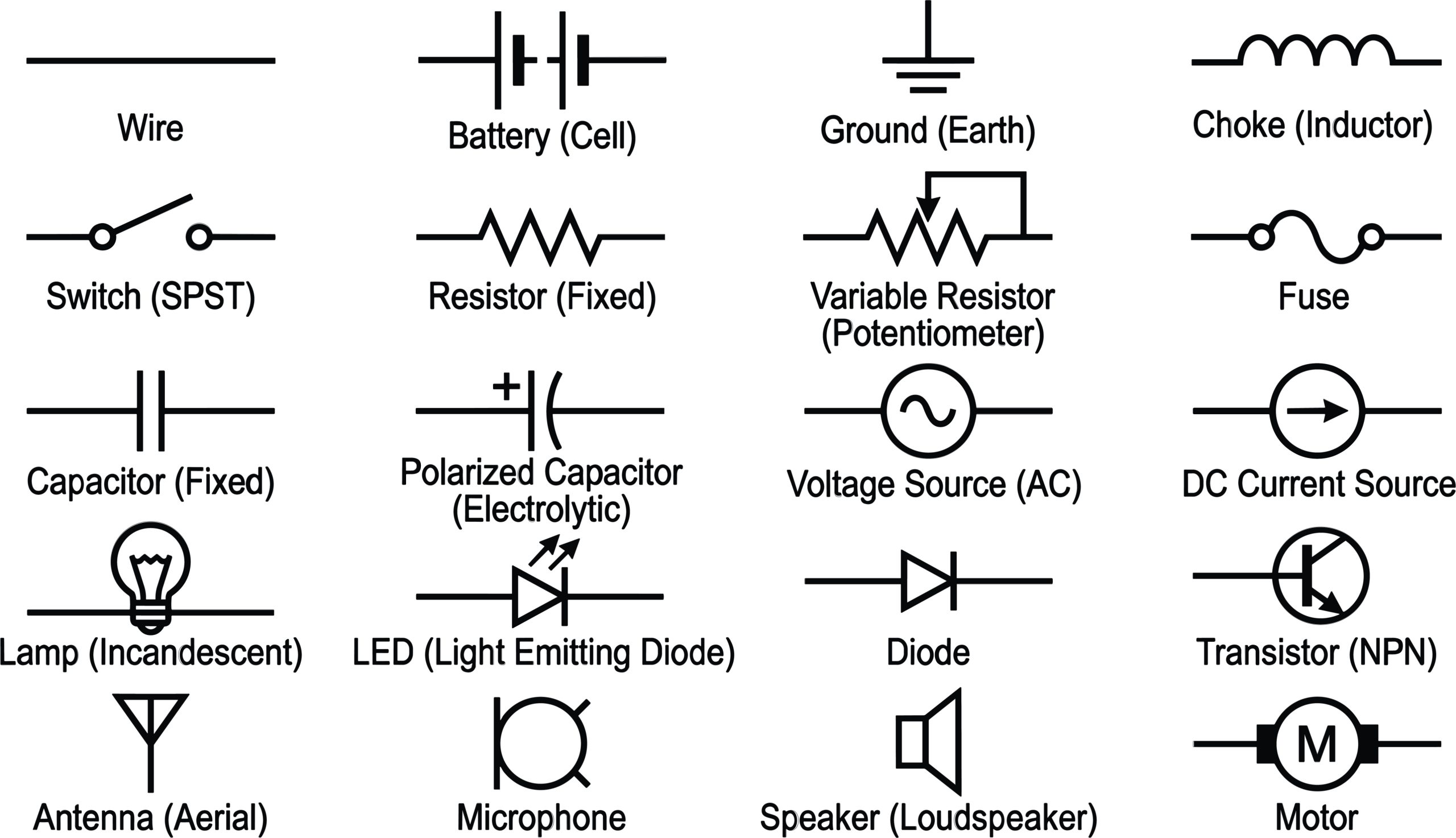
Electrical circuit symbols provide the shared language used to describe an electronic design. They allow engineers, component suppliers and assembly teams to understand how a circuit should operate before any components are placed onto a printed circuit board.
However, a schematic must do more than show electrical intent. It must communicate that intent clearly enough to support component procurement, PCB layout, assembly, inspection and testing. Inconsistent or incorrect symbols can create uncertainty, delay production and increase the risk of costly rework.
What Are Circuit Symbols?
To understand their importance in manufacturing, it helps to begin with their basic purpose.
Circuit symbols are simplified graphical representations of electrical and electronic components. Each symbol identifies a component type or circuit function without showing the component’s physical appearance.
For example, a resistor is represented by a standard schematic symbol rather than a drawing of an axial or surface-mount component. The schematic may then include a reference designator, such as R1, and a value, such as 10 kΩ.
These circuit diagram symbols are connected by lines representing electrical nets. Together, they show how power, signals and data should move through the design.
Why Standardised Circuit Symbols Matter in PCB Design and Manufacturing
Once the purpose of circuit symbols is clear, the need for consistency becomes equally important.
Standardised electrical circuit symbols help everyone involved interpret the same design in the same way. Common conventions are defined through standards and established engineering practices, including IEC (International Electrotechnical Commission) and ANSI (American National Standards Institute) conventions.
Some symbols differ between standards. A resistor, for example, is commonly shown as a rectangle under IEC conventions and a zigzag line under ANSI conventions. Either form can be understood when used consistently.
Problems arise when symbols are ambiguous, poorly labelled or applied differently across the same project. An unclear symbol may leave the PCB designer or assembly partner uncertain about:
- component type and value
- pin numbering and orientation
- polarity requirements
- fitted and non-fitted component options
- power and grounding arrangements
- the intended function of a circuit section
At MPE Electronics, we review customer documentation as part of the preparation for PCB assembly. Clear bills of materials and placement data help our production team build and inspect each assembly against the correct specification.
Common Electrical Circuit Symbols Explained
With those principles established, the following groups cover many of the symbols found in electronic schematics.
Power Supply and Ground Symbols
| Symbol type | Typical function | Why it matters in production | |
| DC supply | 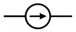 |
Identifies a direct-current voltage rail, such as 3.3 V, 5 V or 12 V. | Incorrect voltage labels can affect test requirements. |
| Battery or cell | 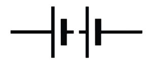 |
Represents a stored electrical power source. | Polarity, voltage and connector details must be clearly defined. |
| Earth ground | 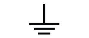 |
Shows a connection intended for physical earth or protective grounding. | This must not be confused with signal ground or chassis ground. |
| Signal ground |  |
Provides a common electrical reference within a circuit. | Poorly defined grounding can contribute to noise, instability and test failures. |
Ground symbols deserve particular attention because several types may appear within one product. Combining them incorrectly during PCB layout can alter circuit performance or compromise safety requirements.
Passive Components: Resistors, Capacitors and Inductors
| Component | Typical function | Key schematic information | |
| Resistor (fixed) | 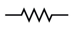 |
Limits current, divides voltage or sets operating conditions. | Resistance value, tolerance and power rating where relevant. |
| Variable resistor | 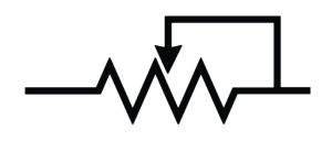 |
Provides an adjustable resistance. | Adjustment method, pin arrangement and required setting. |
| Capacitor | 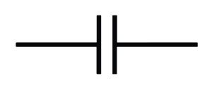 |
Stores charge, filters noise or supports timing functions. | Capacitance, voltage rating, dielectric type and polarity. |
| Inductor | 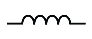 |
Stores energy in a magnetic field and filters current. | Inductance, current rating, resistance and construction type. |
A capacitor symbol may indicate whether the component is polarised. This distinction directly affects assembly. Reversing an electrolytic or tantalum capacitor can cause immediate failure or reduce product reliability.
The symbol alone may not specify every manufacturing requirement. The bill of materials should therefore provide the exact component description and approved part number.
Diodes and LEDs
A diode allows current to flow primarily in one direction. Its symbol indicates the relationship between the anode and cathode, which makes orientation critical.
Related electronic circuit symbols include:
- standard rectifier diodes
- Zener diodes used for voltage regulation
- Schottky diodes used for low forward-voltage applications
- photodiodes that respond to light
- light-emitting diodes (LEDs)
LED symbols normally include arrows pointing away from the diode to represent emitted light. Assembly documentation should also identify polarity and physical orientation clearly, particularly where the LED’s position must align with an enclosure or light guide.
Transistors
Transistors are used for switching, amplification and signal control. Common circuit symbols include bipolar junction transistors and field-effect transistors.
A bipolar transistor symbol identifies the base, collector and emitter. An arrow differentiates NPN and PNP devices. MOSFET symbols identify the gate, drain and source, while also indicating device type.
Accurate pin mapping is essential. Components with similar electrical functions can have different package pinouts. A symbol based on the wrong pin configuration may appear correct on the schematic but produce an unusable PCB layout.
Switches and Relays
Switch symbols show how contacts open, close or change between circuits. They may represent push buttons, toggle switches, rotary switches or electronically controlled switching devices.
Relay symbols usually show the coil separately from the controlled contacts. A schematic should make clear whether contacts are normally open or normally closed when the coil is not energised.
This information affects both functional testing and product behaviour. An incorrect contact designation could make equipment start, stop or signal at the wrong time.
Connectors and Integrated Circuits
Connector symbols represent electrical interfaces between boards, cables, sensors and other assemblies. They should include clear pin numbering and meaningful signal names.
Integrated circuits are often shown as labelled rectangular blocks with multiple pins. The symbol may group pins by function rather than following their physical order around the package.
A single numbering mismatch can affect every assembly produced from the design.
How Engineers Read Schematics Before PCB Assembly
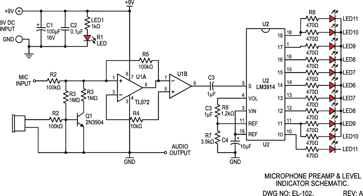
Knowing individual circuit components symbols is only the starting point. Engineers must also interpret the circuit as a complete system.
Before assembly, manufacturing documentation is checked to understand component requirements, polarity, orientation and any special build instructions.
Early collaboration with MPE’s support can help customers identify practical assembly issues before a design enters production.
Unclear polarity and orientation
Diodes, LEDs, electrolytic capacitors, integrated circuits and connectors often require controlled orientation. Ambiguous documentation increases the possibility of incorrect placement.
Footprint mismatches
The electrical pins defined in the schematic must correspond to the physical pads in the footprint. Package naming alone is not enough because similar packages may use different pin arrangements.
Inconsistent IEC circuit symbols
Using IEC circuit symbols alongside alternative conventions is not necessarily incorrect. However, unexplained changes in notation can create ambiguity, particularly in multinational supply chains or older designs.
Missing manufacturing notes
A schematic may describe the electrical circuit without identifying production-specific requirements. These can include fitted options, component substitutions, hand-soldering instructions or configuration settings.
Schematics also provide context during PCB testing. When a board does not behave as expected, engineers use the schematic to trace power rails, signals and component interactions.
For example, a failed output may initially appear to be caused by an integrated circuit. Following the schematic could instead reveal an incorrectly specified pull-up resistor, reversed diode or missing power connection.
This is why electrical circuit symbols are part of the controlled technical information that supports repeatable production.
MPE assembles printed circuit boards supplied or procured through approved PCB fabricators; we do not manufacture bare PCBs. Our electronics manufacturing services focus on converting approved design data into reliable assembled products, with inspection and traceability maintained throughout the process.
Why Partnering With an Experienced PCB Assembly Provider Matters
An established contract electronics manufacturer understands how design information affects procurement, placement, soldering, inspection and testing. That perspective helps identify documentation gaps before they become production problems.
MPE supports low-to-mid-volume and high-reliability assemblies, with flexibility for prototyping, established products and changing requirements. Our IPC-trained production team assembles to specification, and every PCB assembly is inspected individually rather than relying only on batch-level checks.
We also support turnkey box-build, allowing customers to reduce supplier handovers across PCB assembly, wiring, enclosure integration and final product build.
Clear circuit symbols are one part of that controlled process. Combined with accurate bills of materials, validated PCB data, traceability and documented inspection, they help reduce avoidable manufacturing risk.
Discuss Your PCB Assembly Requirements With MPE
Accurate electrical circuit symbols create a clearer route from design intent to dependable production. When symbols, footprints, bills of materials and assembly data agree, manufacturers can procure, build, inspect and test with greater confidence.
MPE Electronics works closely with engineering, procurement and operations teams to identify risks early and support a controlled transition into production. To discuss a new design, an existing assembly or a complete box-build requirement, contact our team.
