
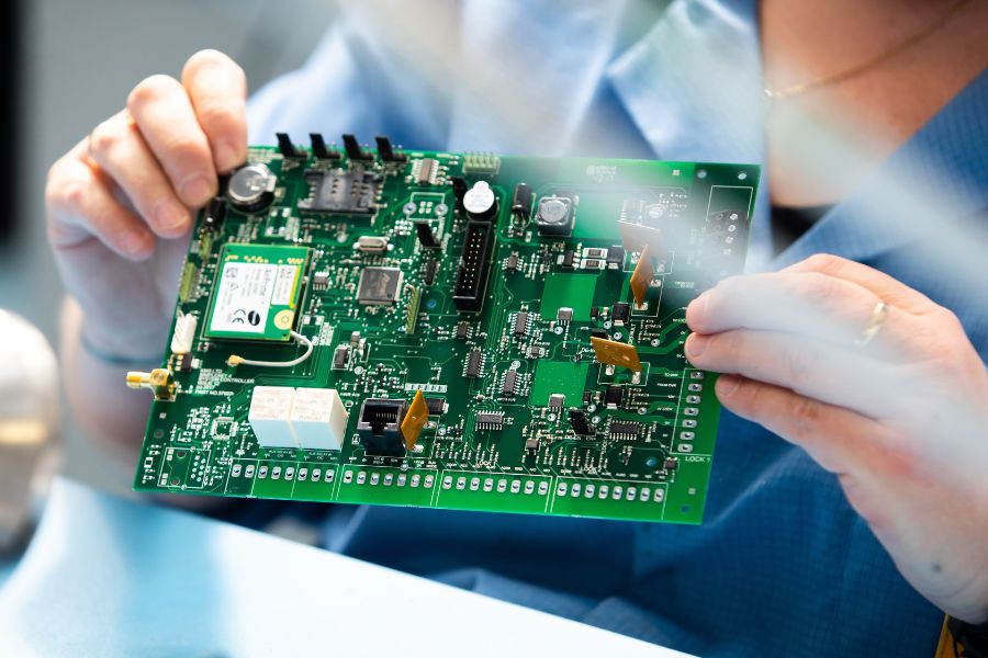
Selecting the right printed circuit board assembly (PCBA) method is a crucial decision for engineers and procurement teams working in industrial and automotive electronics. The primary choice often comes down to surface mount technology (SMT) versus through-hole technology (THT), with each offering distinct advantages and limitations that directly impact product reliability, manufacturability and overall performance. Understanding how SMT and THT differ, and where each is best suited, is essential for optimising production outcomes in these demanding sectors.
Understanding Surface Mount Technology and Through-Hole Technology
To appreciate why the choice between SMT and through-hole matters, it’s important to first clarify what each technology involves. SMT involves mounting electronic components directly onto the surface of the printed circuit board (PCB). These components are usually very small and have metalised terminations soldered onto copper pads on the board. In contrast, through-hole technology requires component leads to be fed through drilled holes on the PCB and soldered on the opposite side. This difference affects everything from design flexibility to mechanical strength.
Industrial and automotive electronics face challenging environmental and mechanical conditions. Knowing how SMT and through-hole assembly methods respond to these demands helps engineers select the most appropriate approach for their projects.
Key Differences Between SMT and Through-Hole for Industrial and Automotive Use
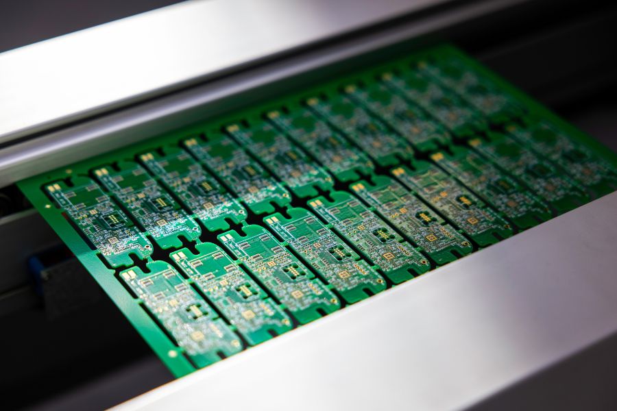
Understanding the main differences between SMT and through-hole technology is vital in industrial and automotive contexts. SMT allows for higher component density because smaller parts can be mounted on both sides of the PCB. This enables more compact designs—ideal for automotive control units or industrial sensors where space and weight are critical. SMT assembly also benefits from faster, automated placement processes that boost production efficiency and consistency.
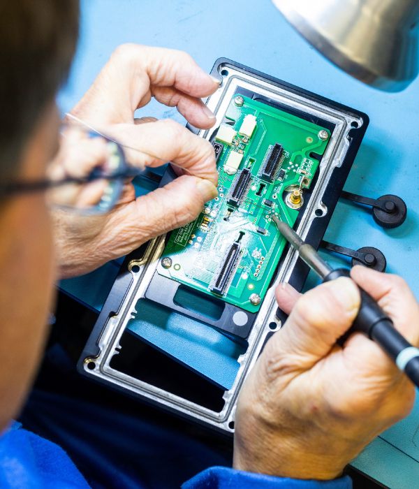
Conversely, through-hole technology provides stronger mechanical connections by physically anchoring components through the PCB. This robustness is particularly important in applications exposed to vibration, shock, or mechanical stress, common in automotive and heavy industry environments. Through-hole components also facilitate easier repairs and modifications since their leads are accessible and more durable.
Another critical factor is compliance with quality standards such as IPC A-610. This internationally recognised standard specifies acceptance criteria for electronic assemblies, including the soldering quality of both SMT and through-hole assemblies. Ensuring conformance to IPC A-610 is essential to meet safety and reliability requirements in industrial and automotive electronics manufacturing.
Weighing SMT vs Through-Hole: Design Flexibility and Production Considerations
Building on the technical differences, it is important to consider how SMT and through-hole technologies affect design and production workflows. SMT supports greater design complexity and miniaturisation in electronic products. Small outline packages like resistors, capacitors, and integrated circuits can be densely placed, enabling multifunctional circuit boards within limited volumes.
Production volume is another key consideration. SMT is well suited to high-volume manufacturing due to its automation advantages. Through-hole assembly tends to be more time-consuming and costly but is justified for applications needing stronger mechanical connections. Many complex boards use a hybrid approach, combining SMT and through-hole components to capitalise on the benefits of both technologies.
What this means in practice for engineering and procurement teams
Deciding between SMT and through-hole technologies involves practical steps that align with project goals:
- Specification: Assess the environmental and mechanical stresses the PCB will face; choose through-hole for high-stress applications and SMT where space constraints dominate.
- Component Selection: Prioritise IPC A-610 compliant SMT components for automated, high-volume assembly; select through-hole parts when durability and ease of repair are required.
- Compliance: Confirm that PCB assemblies meet IPC-610 standards; ensure manufacturing partners have proven expertise in both SMT and through-hole processes.
- Production Planning: Factor in expected volumes and budget; select SMT for large-scale runs and through-hole or hybrid assembly for specialised or smaller batch production.
- Testing and Quality Control: Employ strict inspection methods based on IPC standards; emphasise mechanical joint integrity for through-hole components.
Common Misconceptions About SMT and Through-Hole Technology
It’s vital to dispel common myths around SMT and through-hole technology. One is that SMT is always better because it is newer and more advanced. While SMT offers many benefits, it is not a universal solution. Through-hole technology remains crucial for reliable, mechanically robust connections where physical stresses are significant.
Another misconception is that SMT components are inherently fragile. Properly designed and soldered SMT parts, meeting IPC-610 standards, can withstand harsh conditions. In contrast, poor SMT assembly can cause failures just as weak through-hole soldering can.
Understanding the real strengths and limitations of both methods helps engineers avoid costly mistakes during design and manufacturing. More details on these advantages and disadvantages can be found in our articles: Advantages and disadvantages of surface mount technology and What is Through Hole Technology.
Conclusion: Making the Right Choice Between Surface Mount vs Through-Hole for Industrial & Automotive PCBs
Choosing between surface mount technology and through-hole assembly for industrial and automotive PCBAs requires carefully balancing performance, mechanical demands, cost and production scale. SMT assembly provides compactness, speed, and design flexibility suited to many modern electronics. Through-hole technology offers greater mechanical strength and is often preferred in harsh environments.
Compliance with IPC A-610 standards is critical regardless of the chosen assembly method. We regularly collaborate with engineers and procurement teams to ensure PCB assembly decisions align with technical requirements and quality expectations.
To explore how SMT or through-hole technology can best suit your industrial or automotive PCBA projects, contact MPE to discuss your specific assembly requirements. Our expertise in electronics manufacturing supports optimising your design and production processes for reliable, high-quality results. Contact MPE Electronics on +44 (0)1825 764822 or email enquiries@mpe-electronics.co.uk.
FAQ
Is surface-mount better than through-hole?
Surface-mount technology is not inherently better; it offers benefits like smaller size and automated production. Through-hole technology provides stronger mechanical connections. The best choice depends on your application’s mechanical, environmental, and space requirements.
What is the difference between through-hole and SMD?
Through-hole components have leads inserted through PCB holes and soldered on the opposite side. Surface mount devices (SMD) are soldered directly onto the PCB surface without leads going through holes, allowing for more compact, dense assemblies.
What are the disadvantages of SMD?
SMD components can be harder to repair or replace manually and require precise soldering processes. They may also be less mechanically robust in very high-stress environments if not properly designed.
How do surface mount device resistors differ from through-hole resistors?
Surface mount resistors are smaller, leadless, and mounted on PCB pads, enabling tighter circuit layouts. Through-hole resistors have wire leads inserted into PCB holes, offering easier manual handling and stronger mechanical attachment.
